About
Foxtrot is a fast viewer for STEP files, a standard interchange format for mechanical CAD. It is an experimental project built from the ground up, including new libraries for parsing and triangulation.
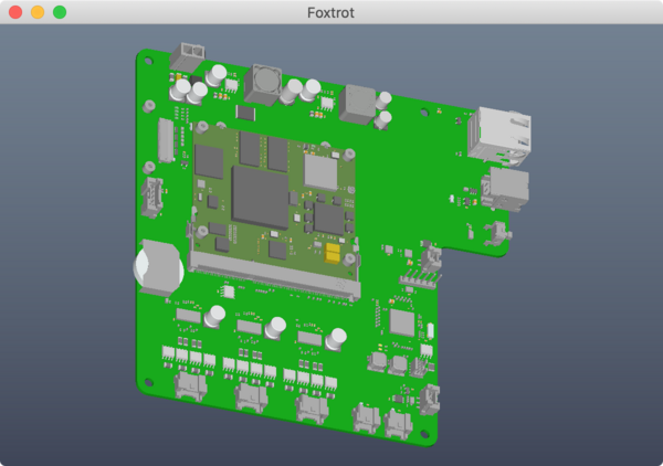
In a mere 8.7 KLOC of Rust (plus 39 KLOC of generated parser), it can render this PCB, going from application start to first frame in 981 milliseconds:
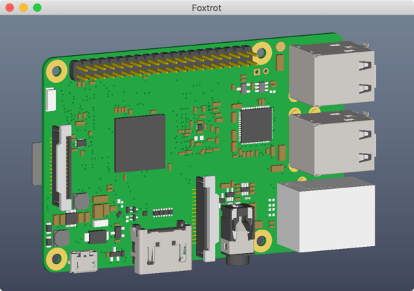
(this is harder than it looks)
The project includes command-line utilities, the desktop application shown above, and a demo running the same code in a browser using WebAssembly.
This was a group project at the Formlabs 2021 Hackathon, built by
- Henry Heffan (parsing and b-spline)
- Evan Matteson (experiments with traits)
- Zhangchao Wei (graphics and camera)
- And myself (triangulation, shaders, architecture, web demo)
At the end of the hackathon, we could render our most challenging test file in 2.2 seconds, in glorious RGB-o-vision:
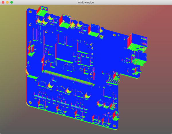
I've continued to develop it afterwards, culminating in this writeup; that test file now loads in 971 milliseconds, with fewer errors and more reasonable shading.
It's still nowhere near industrial strength, but I consider it a surprisingly successful project, and worth documenting and open-sourcing.
Why?
The motivation of the project are summed up in my Hackathon pitch slide:
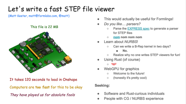
(As noted above, Foxtrot loads that file in 0.97 sec, which I'd call a success)
This project was also inspired by Embedded Ventures' RFP and related discussions.
Coming in from a software perspective, it's easy to see that modern mechanical CAD is terrible – kernels and UIs date back to the 80s, there's no version control, and they've mostly missed the boat on open source.
It's hard to plot a course to a better future without understanding why things are they way they are. Modern manufacturing infrastructure is built around NURBS and STEP files, like it or not, so I wanted to learn more about how they work.
Architecture
Like an iceberg, most of the Foxtrot infrastructure is below the water line.

The grey, yellow, and red boxes are doing the vast majority of the work: they represent 4.4KLOC (not including the autogenerated parser), while the GUI is a mere 701 LOC.
We'll take a tour through the pipeline, step by step (heh), and hopefully emerge with a better understanding of the system.
EXPRESS and parser generation
If you open up a STEP file,
you'll notice that it's nominally human-readable:
there are a bunch of entities which are assigned IDs (with a #)
and refer to each other and primitive types.
...
DATA;
#1 = APPLICATION_PROTOCOL_DEFINITION('international standard',
  'automotive_design',2000,#2);
#2 = APPLICATION_CONTEXT(
  'core data for automotive mechanical design processes');
#3 = SHAPE_DEFINITION_REPRESENTATION(#4,#10);
#4 = PRODUCT_DEFINITION_SHAPE('','',#5);
#5 = PRODUCT_DEFINITION('design','',#6,#9);
#6 = PRODUCT_DEFINITION_FORMATION('','',#7);
#7 = PRODUCT('PCB','PCB','',(#8));
#8 = PRODUCT_CONTEXT('',#2,'mechanical');
#9 = PRODUCT_DEFINITION_CONTEXT('part definition',#2,'design');
#10 = SHAPE_REPRESENTATION('',(#11,#15,#19),#23);
#11 = AXIS2_PLACEMENT_3D('',#12,#13,#14);
...
However, it's not obvious what entities to expect, or what types their arguments should be. Luckily, the file format is described by a separate schema, written in the EXPRESS language.
This implies a straightforward workflow: we should parse the EXPRESS schema, then use that information to generate a parser for STEP files.
(During the hackathon, we decided this would be overkill, so we instead wrote a bespoke parser generator for the subset of STEP entities that appeared in our example files; I implemented the EXPRESS parser & generator afterwards)
Though the workflow is theoretically straightforward, it's hampered by the fact that EXPRESS is a bad format. For example, the standard includes a language syntax definition, followed by the warning
NOTE: This syntax definition will result in ambiguous parsers if used directly.
The EXPRESS language is also too powerful: as well as describing entities and types, it includes nigh-arbitrary constraints and its own syntax for functions. Here's how to build an orthonormal basis, according to ISO 10303-42:
FUNCTION first_proj_axis(z_axis : direction;
                         arg : direction) : direction;
LOCAL
  x_axis : direction;
  v : direction;
  z : direction;
  x_vec : vector;
END_LOCAL;
  IF NOT EXISTS(z_axis) THEN
    RETURN (?);
  ELSE
    z := normalise(z_axis);
    IF NOT EXISTS(arg) THEN
      IF (z.direction_ratios <> [1.0, 0.0, 0.0]) AND (z.direction_ratios <> [-
      1.0, 0.0, 0.0]) THEN
        v := dummy_gri||direction([1.0, 0.0, 0.0]);
      ELSE
        v := dummy_gri||direction([0.0, 1.0, 0.0]);
      END_IF;
    ELSE
      IF arg.dim <> 3 THEN
        RETURN (?);
      END_IF;
      IF cross_product(arg, z).magnitude = 0.0 THEN
        RETURN (?);
      ELSE
        v := normalise(arg);
      END_IF;
    END_IF;
    x_vec := scalar_times_vector(dot_product(v, z), z);
    x_axis := vector_difference(v, x_vec).orientation;
    x_axis := normalise(x_axis);
  END_IF;
  RETURN (x_axis);
END_FUNCTION; -- 10303-42: geometry_schema
Looks like fun, right?
All of this is explained in non-free standards, which are so rarely seen in the wild that I couldn't find them on Sci-Hub or libgen. Thus, our hackathon budget went towards
- ISO 10303-11:2004 ($250)
- ISO 10303-21:2016 ($48)
- ISO 10303-242:2020 ($74)
(Fun fact: the latter is distributed as a 300 MB file named
ISO+10303-242-2020.pdf, which is actually a ZIP archive with
an incorrect file extension)
By constantly testing against the AP214 schema,
I eventually implemented
an EXPRESS parser
using nom
that could read the whole thing.
With a bunch more work
(and ignoring everything that wasn't a type or entity definition),
I coaxed the EXPRESS syntax tree into a form that could be translated into
Rust types, then generated a nom parser to read STEP files.
The resulting code
is huge (39KLOC),
so it's isolated into its own crate to improve compilation time.
STEP file parsing
As it turns out, STEP files are also bad (surprise!).
The EXPRESS schema defines a full class hierarchy of possible entities, with everything that you'd expect (and fear) in a robust object-oriented language:
- Abstract virtual classes
- Redefining inherited parameters with more specific types
- The "Diamond of Death"
- Ada-like constraints on anything
- Four different generic container types (array, list, bags, and sets)
- "Total Coverage Subtypes" (I don't know what this is but it scares me)
On the other hand, the spec is typeset in LaTeX, so that's nice.
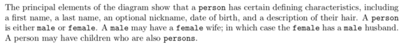 Also featuring: outdated ideas about gender!
This adds up to a system where the happy path is easy, but there's fractal complexity in the corners of the standard. The vast majority of a STEP file is lines like
#8 = PRODUCT_CONTEXT('',#2,'mechanical');
which is perfectly sensible, defines a single entity,
and parses to a single struct ProductContext.
However, consider the following definition:
#5307 = ( GEOMETRIC_REPRESENTATION_CONTEXT(3)
          GLOBAL_UNCERTAINTY_ASSIGNED_CONTEXT((#5311))
          GLOBAL_UNIT_ASSIGNED_CONTEXT((#5308,#5309,#5310))
          REPRESENTATION_CONTEXT('Context #1',
                                 '3D Context with UNIT and UNCERTAINTY') );
Looking at the class hierarchy from the EXPRESS schema, REPRESENTATION_CONTEXT
is the parent of all three other classes listed here;
this entity is an ad-hoc, unnamed type which is the union of the three
leaf types.
This adds extra complexity: the parser now needs to know about the class hierarchy at runtime, to decode these arbitrary combinations of types.
Complaints aside, the autogenerated parser works fine.
It runs in three passes:
- Remove comments and whitespace
- Split into individual entities
- Parse entities
The first two steps are single-threaded but fast, as they're simply
a series of memchr searches.
Entity parsing is run in parallel using Rayon,
as each entity declaration is independent.
Running on a relatively large (22 MB) example file, parsing takes roughly 363 ms, meaning it runs at 60 MB/sec on a 2013 Macbook Pro.
I would classify this as okay in terms of performance; there's definitely room for improvement, but it's not offensively slow.
The result of the parsing step is a flat vector of entities,
which are each an enum selecting from all known entity types
(plus special cases for lines that failed to parse or built anonymous types).
These entities refer to each other in a tangled web.
For example, one of our test files was an extruded rectangle with a hole cut out of the center. This seems like a very simple file:
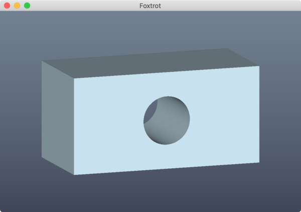
Here's about 30% of the parsed STEP entity graph (click for the full version):

As you can see, even with a trivial file, there's a lot going on!
Triangulation
Given a set of entities, the next step is to convert surfaces into triangle meshes.
In STEP files, 3D solids are defined as a list of faces, which are each made of
- A 3D surface (sphere, cylinder, etc)
- An edge loop bounding the patch (built from lines, circular arcs, b-spline curves, etc)
These are mix-and-match: for example, you can have a patch on a cylinder bounded by b-spline curves. Because of this flexibility, I built a pipeline which separates curves, surfaces, and triangulation:

This runs in parallel across every surface, then combines the resulting meshes before sending them to the GPU.
Edge loops
The first step is relatively obvious: given a curve, sample it and build an edge loop built from 3D points. We didn't get too fancy for curves, picking a fixed number of points to sample b-spline and NURBS curves, and a fixed angular resolution for circular arcs.
Lowering from 3D to 2D
Lowering points from 3D to 2D is the first hard part. This requires parameterizing the surface with a new (UV) coordinate system, then finding a general mapping from 3D to 2D that preserves useful properties.
Here's an example of why this can be tricky: A 3D cylinder can be defined as the cylinder surface bounded by two edge loops, each capping one end with a full circle.
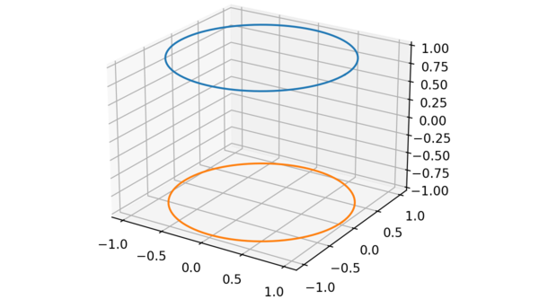
The naive projection for a cylinder surface is polar, i.e. θ-Z coordinates.

However, this coordinate system wraps around from 𝛑 to -𝛑 on the X axis, so you can't triangulate it with an algorithm for planar 2D triangulation!
I had already written code for Constrained Delaunay Triangulation, so I was wedded to the idea of finding a planar projection for each surface.
For cylinders, the trick is to convert Z height to a scale factor, so this cylinder becomes

This projection is suitable for planar triangulation! I found similar tricks for spheres and toruses, both of which have similar wrapping edges.
(Of course, the resulting 2D Delaunay triangulation isn't necessarily as good in 3D, because the 3D-to-2D transformation doesn't preserve distance. For a hackathon project, I decided this was fine.)
For b-spline surfaces, Henry ported algorithms from The NURBS Book to find the closest point in UV coordinates. This is by far the slowest step in triangulation, because it's an iterative (gradient descent) search rather than a closed-form solution.
2D triangulation and Steiner points
The resulting 2D set of points and edges is triangulated with my own implementation of Constrained Delaunay Triangulation.

I'm using a combination of "A faster circle-sweep Delaunay triangulation algorithm" and "Sweep‐line algorithm for constrained Delaunay triangulation". The former is fast and easy to implement; the latter (mostly) explains how to constrain fixed edges.
This part of the project is suitable for re-use, and I published it as a separate, standalone crate.
Applying the resulting 2D triangulation to the original (unprojected) 3D points will build a patch of the mesh. However, it isn't always as pretty when projected into 3D.
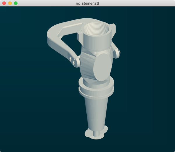
Consider a section of a torus with a cutout, as seen in this model. Projected into 2D, it looks like this:

This seemingly-reasonable triangulation looks bad in 3D, because straight lines in 2D actually represent curves when projected back to 3D:
There are probably many ways to solve this, but one simple trick is to add Steiner points to the triangulation in 2D:

These points smooth out the 3D triangulation by creating a denser mesh:
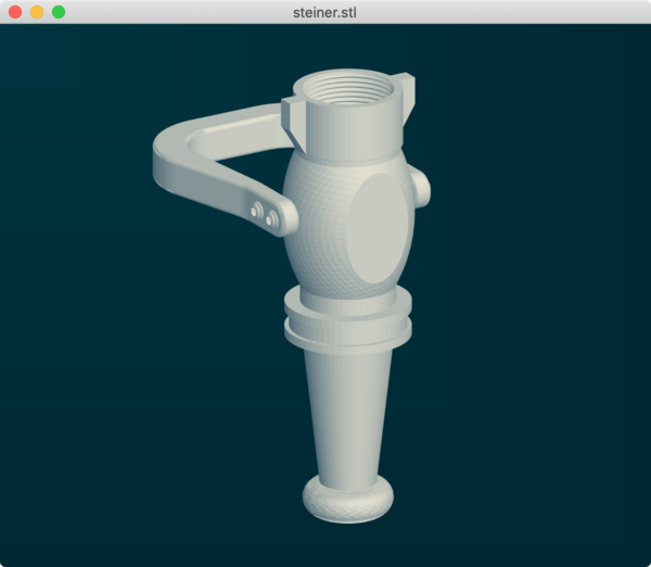
This is done naively (using a fixed number of points in a grid), but works well enough for the project.
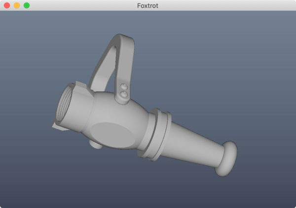
Rendering with per-vertex normals also hides a lot of sins in the meshing. The above screenshots show the underlying triangle mesh, which has crinkles on the bottom nozzle; rendering with per-vertex normals looks much smoother, even though the triangulation is the same:
GUI
After all of this is done, the GUI is almost an afterthought.
It's less than 1 KLOC, uses wgpu-rs,
and simply draws triangles to the screen
with a mouse-controlled camera.
(Having written several mesh viewers in the past,
I'm very comfortable with the matrix math of camera control.)
Triangulation returns vertex and triangle arrays. Each vertex includes
- Position
- Normal
- Color (defaulting to grey)
Triangles are built as triples of indexes into the vertex array.
This is all pretty standard stuff, and WebGPU has reasonable support for indexed rendering.
The only tricky part here is using WGSL for shaders.
This is a brand new shader language,
and is the default in wgpu 0.8.0,
but documentation and tutorials are sparse.
Luckily, we're not doing anything complicated,
so I mostly pattern-matched against examples.
One more thing...
Because the whole stack is written in Rust, it can be trivially cross-compiled to WebAssembly and run in a modern browser!
Once I realized this, I had to do it, obviously. The result is "Foxtrot 365", shown here rendering a robot arm:
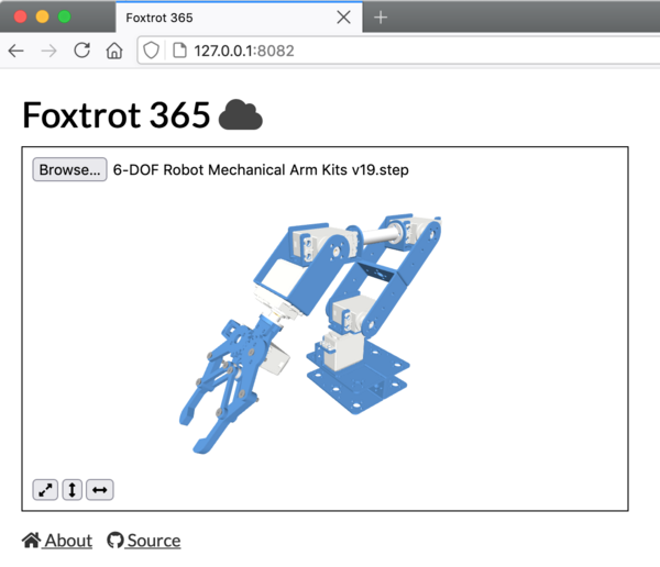
This is a web application which accepts a STEP file through the selector, parses and triangulates it, and renders it in a WebGL canvas.
The core is a single function
which takes in a String representing the STEP file,
and returns a Vec<f32> that represents the triangle array.
This is an bindable wrapper around the parsing and triangulation subsystems.
This function runs in a WebWorker (to avoid blocking the browser UI),
and drops the mesh into a Three.js viewport.
It's theoretically possible run the desktop GUI in the browser,
since it's using winit and
WebGPU,
but that seemed a bridge too far.
(Yes, I do draw the line eventually)
Running on the same test model as before, it loads in 5.1 seconds, so there's a roughly 5x overhead. This is using a single worker, while the desktop app uses a thread pool. Running the desktop app without multithreading, the same file loads in 1.48 seconds, so the true WebAssembly overhead is about 3.4x.
Looking back at my original proposal, this is still 23x faster than Onshape, and is completely local: there's no huge server in The Cloud handling your models!
(Interestingly, this also indicates that multithreading isn't helping that much in the desktop app, since it's a mere 50% speedup)
Conclusions
It's hard to draw a single conclusion from this project.
We set out trying to write a fast STEP file viewer, built something that mostly works on many models, and recognize that bringing it to "totally works on all models" would be an enormous investment.
EXPRESS and STEP files both feel very dated, and it's hard to imagine someone using all of the features in there; maybe it's one of those cases where everyone uses a different subset of the features? As one example, Foxtrot uses 26 entity types, and the AP214 standard defines 915 (!!).
Rust and WebGPU are both great,
although build time for the main GUI has become painful:
after touching main.rs, it takes a full 30 seconds to rebuild!
(I think the slow build time is mainly WebGPU's fault;
an incremental rebuild of the step_to_stl command-line utility
takes only 4 seconds)
Finally, the hackathon team did a great job – over the course of three days, we achieved far more than I had expected!
Source
The copyright on this project is held by Formlabs, and the company has open-sourced it under Apache / MIT, which is a common dual license in the Rust ecosystem.
The repository for Foxtrot is hosted on Github.
It's set up as a single Cargo workspace, but that may change in the future (since that makes it hard to publish the GUI as a crate).
Thus far, we don't have a CLA; if you're outside of Formlabs and want to contribute, let me know and I'll check with the legal team.
Related work
Software
- Truck: The beginnings of a CAD kernel in Rust. I really like the philosophy spelled out in the README, which has a well-argued roadmap for incrementally building the future of CAD.
iso-10303: Another Rust project to parse EXPRESS and generate a STEP parser, very similar in spirit to Foxtrot'sexpresssubsystem (down to generating a gigantic file namedap214.rs)ruststep: Exactly what it says on the label- OpenCascade: the open-source CAD kernel that everyone uses and no one loves
- SolveSpace: A neat open-source CAD tool
- SINTEF Geometry Toolkit: Another set of CAD libraries
Papers
- Delaunay Triangulation for Curved Surfaces: Perhaps a systematic way to make triangulation better?
- Watertight Trimmed NURBS: Turns out, you can't actually intersect NURBS
- Implicitization using Moving Curves and Surfaces: Convert your NURBS patches into implicit surfaces (in the form of huge determinants)!